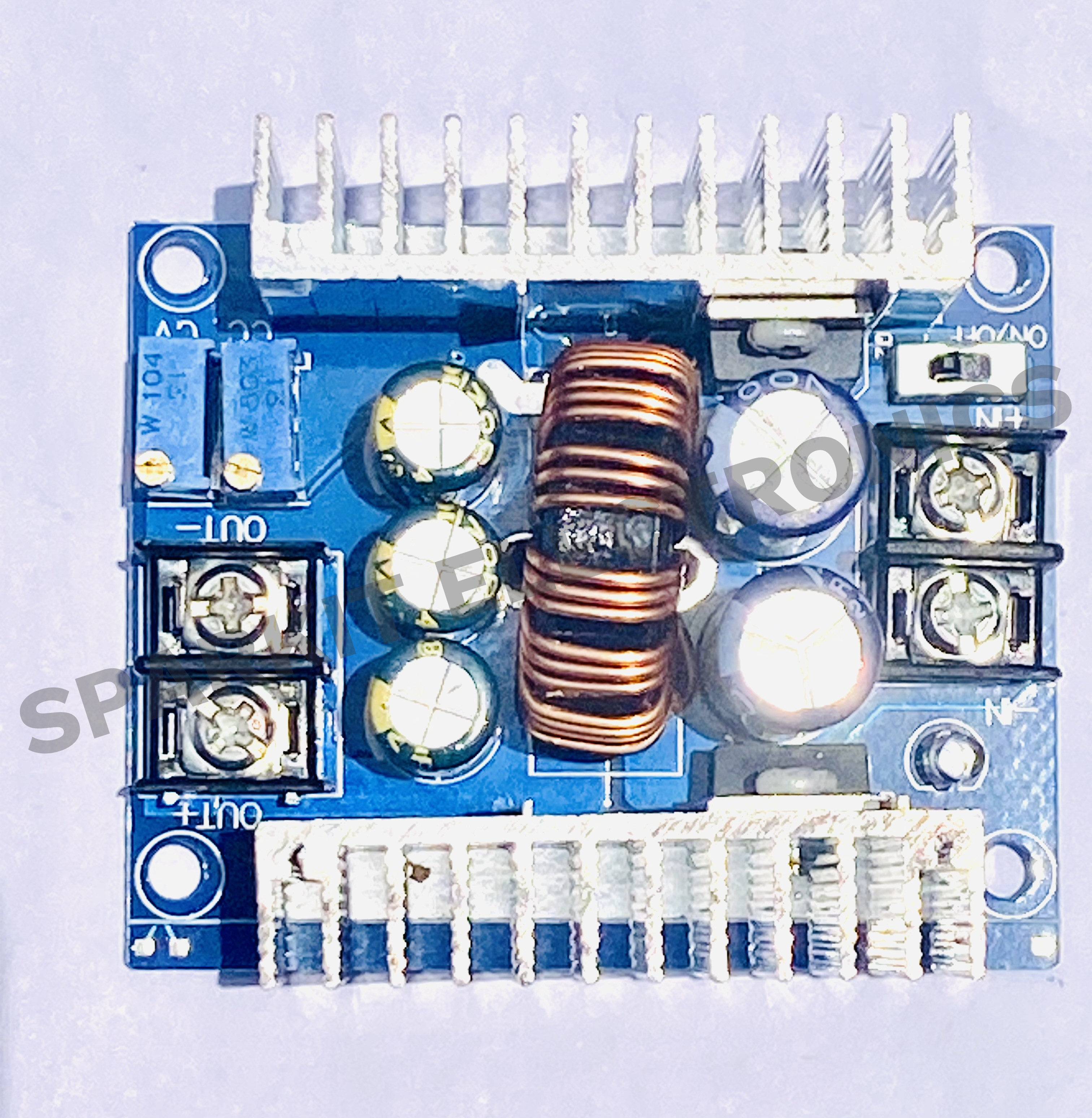
SZBK07 DC-DC Buck Converter 300W 20A Step-down CC CV Module
SKU: SPKPOW002 · Category: Power Modules › Step Down Modules
RWF 13,500
In stock
Description
This is a powerful adjustable step-down converter for projects that need much more current than small modules like the LM2596 can give. It takes a DC supply between 6V and 40V and converts it to any lower voltage between about 1.2V and 36V, delivering up to 20A and 300W. Because it is a switching converter rather than a linear regulator, most of the power reaches your load instead of being burned off as heat, with efficiency claimed at 95% or better.
What makes it special is that it controls both voltage (CV) and current (CC). Turn one multi-turn potentiometer to set the output voltage, and the other to set the maximum current the module will allow. When your load tries to draw more than that limit, the module holds the current steady and lets the voltage drop instead. That turns it into a small bench power supply, a battery charger, an LED driver or a safe power source for motors, pumps and 12V equipment.
The module is built for real loads: two aluminium heat-sinks cool the power devices, a large toroid inductor and low-resistance electrolytic capacitors smooth the output, and heavy screw terminals hold thick wire securely. An ON/OFF slide switch lets you turn the output on and off without disconnecting the supply.
Features
- Wide input range: 6V to 40V DC
- Adjustable output from about 1.2V up to 36V
- Up to 20A and 300W (15A recommended for continuous use, with a fan)
- Constant-current (CC) and constant-voltage (CV) control with two multi-turn potentiometers for fine adjustment
- High efficiency around 95% to 97% (24V to 12V at high current)
- Short-circuit protection with self-recovery (not meant for long shorts)
- Two aluminium heatsinks on the power devices
- ON/OFF slide switch on the board
- Strong 30A screw terminals for input and output
- Four mounting holes in the corners
- Low output ripple — about 50mV
Specifications
- Type: non-isolated step-down (buck) DC-DC converter
- Input voltage: 6V – 40V DC (10V – 40V suggested for best results)
- Output voltage: 1.2V – 36V DC, adjustable (the output can never be higher than the input)
- Output current: 20A maximum; 15A recommended continuous, with a cooling fan
- Output power: 300W maximum
- Efficiency: about 95% – 97% (seller figure, 24V in, 12V out)
- Switching frequency: about 180kHz
- Output ripple: about 50mV (seller figure)
- Operating temperature: −10°C to +75°C
What the power limit means in practice. The module is limited to both 20A and 300W, so the current it can give goes down at higher output voltages:
| Output voltage | Max current | Power |
| 5V | 20A | 100W |
| 12V | 20A | 240W |
| 15V | 20A | 300W |
| 24V | 12.5A | 300W |
| 36V | 8.3A | 300W |
Board structure description
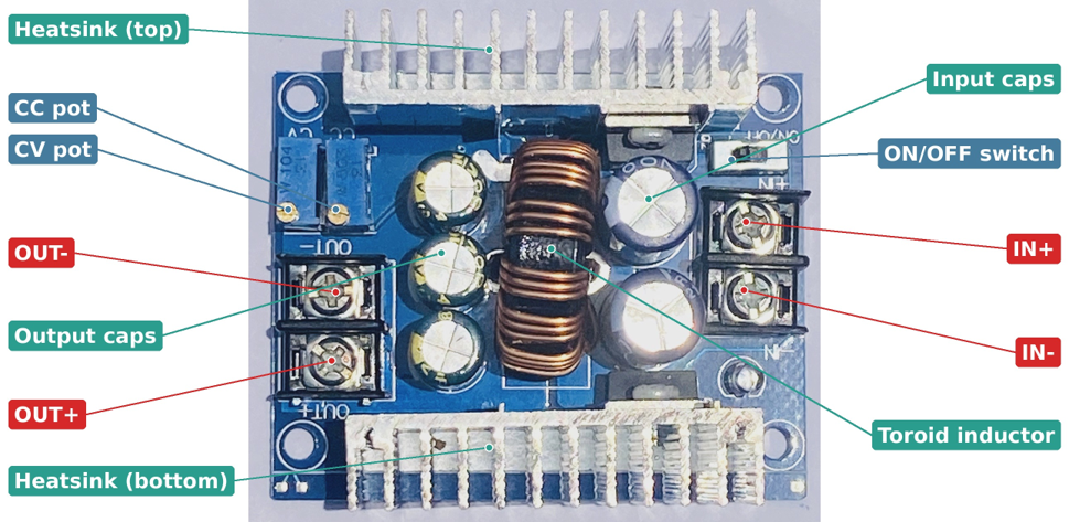
- IN+ / IN− (right-hand terminal block) — positive and negative from your DC supply, 6V to 40V
- OUT+ / OUT− (left-hand terminal block) — regulated output to your load
- CV pot (left blue potentiometer) — sets the output voltage
- CC pot (right blue potentiometer) — sets the maximum output current
- ON/OFF switch — turns the output on and off
- Two heat-sinks — keep the power devices cool; the module gets hot at high power
Getting started: setting voltage and current
Always set the voltage before connecting your device. A new module can be set to any voltage, including one high enough to damage a microcontroller.
- Use thick wire (at least 2.5mm², and thicker for 10A or more). Fix the wires firmly under the screws.
- Connect your DC supply to IN+ and IN−. Check the polarity twice — no reverse-polarity protection is mentioned, and a reversed supply can destroy the module.
- Leave the output disconnected from your load. Connect a multimeter (DC volts) to OUT+ and OUT−.
- Switch the supply on and set the ON/OFF switch of the module to ON. If the output is dead, try the other switch position.
- If the output voltage just follows the input and doesn't change, turn the CV pot counterclockwise 20 turns or more until the module starts regulating. These are multi-turn pots and can take many turns to react.
- Turn the CV pot slowly until the multimeter shows the voltage you need (clockwise raises the voltage, counterclockwise lowers it).
- Quick check of which pot is which: turn one pot a few turns. If the unloaded output voltage changes, it is the CV pot. If nothing changes, it is the CC pot.
- Set the current limit (CC). Switch the supply off. Connect a dummy load (for example a car headlight bulb or a power resistor), put an ammeter in series with it, switch on, and turn the CC pot until the ammeter shows the limit you want. When the load asks for more, the module will hold that current and lower the voltage.
- Switch everything off, connect your real load to OUT+ and OUT−, then switch on again and check the voltage under load.
Setting CC by shorting the output through a meter
Many people set CC by connecting a multimeter on its current range directly across OUT+ and OUT−, then adjusting the pot. This works, but only for short moments and only up to the meter's range (typically 10A and fused). Never do this above 10A, and never leave the output shorted for long — the module can only survive short circuits briefly.
Good to know
- Input must be higher than output. This module only steps down. For a stable output, keep the input at least a few volts above the output voltage.
- Big voltage drops reduce the safe current. The larger the difference between input and output, the more heat the module makes — lower the current accordingly.
- Cooling: if the module goes over about 65°C, add a fan blowing over the heat-sinks. For continuous output near 15A, a fan is strongly recommended.
- Size your supply. The input current is roughly (output power ÷ input voltage). For example, 12V at 15A (180W) from a 24V supply needs about 8A at the input.
- Non-isolated: the input and output are not electrically separated. Treat the negative terminals as shared.
- No short circuits for long: self-recovery protects against brief shorts, not a permanent short.
- Charging batteries: the CC/CV characteristic suits battery charging, but the module has no charge-termination. Set CV to the battery's full-charge voltage, set CC to a safe charge current, and don't leave it unattended.
- Pairing with microcontrollers: to power an ESP32 or Arduino, set the output to 5 V (or 3.3V for 3.3V boards) with no load connected, then connect your board. For small loads, the LM2596 module is a cheaper choice.
Applications
- Adjustable bench power supply for electronics work
- Battery charger (lead-acid, lithium) with current limiting
- LED driver — constant current for high-power LEDs
- Powering 12V equipment (routers, cameras, pumps, fans) from 24V or 36V sources
- Solar panel and DC power-system voltage conversion
- Motor and pump speed projects and robotics power supplies