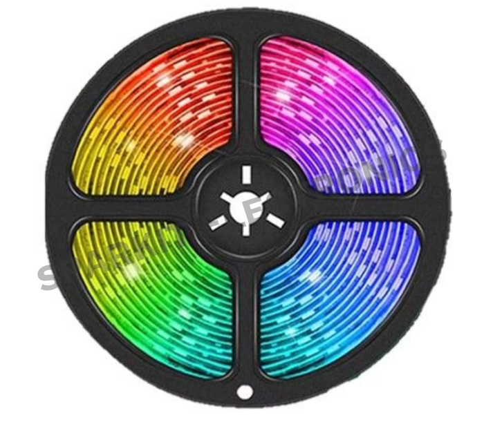
WS2812B Addressable RGB LED Strip 5V 5m 300 LED IP67 Waterproof Pixel Strip
SKU: SPKCON006 · Category: Consumables › Led Strips
RWF 10,800
In stock
This is a 5 metre strip of individually addressable RGB LEDs, made for projects where one colour for the whole strip is not enough. It carries 300 WS2812B pixels (60 per metre) on a flexible white PCB, sealed in an IP67 silicone sleeve so it can be used in damp or dusty places such as shopfronts, signs, outdoor walkways, vehicles, bathrooms, kitchens and garden features where ordinary open strips would not survive. It runs from a 5VDC supply and is controlled with a single data wire from an Arduino, ESP32 or similar board.
What makes it special is that every pixel has its own control chip. Each LED package holds a red, a green and a blue emitter plus a WS2812B driver. The data you send travels along the strip pixel by pixel: each pixel takes its own colour value (8 bits per colour, about 16.7 million colours) and passes the rest on to the next one. That lets you set every LED to a different colour and brightness, so you can build rainbows, chasing lights, progress bars, level meters or status indicators, all from one pin. Ordinary 12V RGB strips cannot do this, because they show one colour across the whole strip at once.
The strip has a 3-pin JST-SM connector (+5V, data, GND) at the input end and a separate red and white lead pair for feeding power straight from your supply. Power is the part to plan for: at full-brightness white the strip can draw up to 18A (90W), but normal colours and animations use only a fraction of that. This page explains how to size your supply and how to limit current in code.
Features
- 300 individually addressable RGB pixels (60 LEDs per metre), 5m long
- Each pixel set to its own colour and brightness: about 16.7 million colours
- Single-wire data control: only one microcontroller pin needed
- Works with Arduino, ESP32, ESP8266 and other boards, using the FastLED or Adafruit NeoPixel libraries
- 5VDC operation
- IP67 silicone sleeve for dust and water protection
- Flexible white PCB with clearly marked +5V / DIN / GND pads and an arrow showing data direction
- 3-pin JST-SM connector at the input, plus a separate red and white power lead pair for direct power feeding
- Can be cut to length at the marked pads, and extended by connecting the DO end to the next strip's DIN
Specifications
- Type: Addressable RGB LED strip, pixel type
- LED / driver chip: WS2812B (RGB LED with built-in driver)
- Number of LEDs: 300 (60 per metre)
- Length: 5m
- Operating voltage: 5VDC
- Rated power: 90W (label figure, all LEDs at full white)
- Maximum current: about 18A (about 60mA per pixel at full white)
- Typical current: about 2A – 7A for normal colours and animations (lower/moderate brightness)
- Colour depth: 24-bit (8 bits per colour), about 16.7 million colours
- Control signal: single-wire data, about 800kHz; colour order GRB
- Frame update time: about 9ms for all 300 pixels (calculated)
- Protection: IP67 silicone sleeve (label figure)
- PCB colour: White
- Connector: 3-pin JST-SM; red = +5V (VCC), green = data (DAT), white = GND
- Power leads: Loose red (+5V) and white (GND) wires with bare ends
What the power rating means in practice
The 90 W figure is the worst case, with all 300 LEDs at full white. You will rarely run it like that. The current depends on colour and brightness:
Use Approx. current Approx. power
All LEDs full white, 100% brightness 18A 90W
Full white at 50% brightness 9A 45W
One colour only (e.g. red) at full brightness 6A 30W
Colourful animation, moderate brightness 4 – 7A 20 – 35W
Test pattern at about 20% brightness 1.5A 8W
Strip structure description
- Input end, 3-pin JST-SM connector — red = +5V, green = DIN (data in), white = GND. Connect the data wire to your microcontroller.
- Input end, loose red and white leads — red = +5V, white = GND. Use these to feed power directly from your 5 V supply. They are the same +5V and GND lines as on the connector.
- Input pads (+5V / DIN / GND) — printed on the strip, with an arrow showing the direction of the data.
- Output pads (+5V / DO / GND) — at the far end. DO passes the data on, so another strip can be joined here.
- Silicone sleeve — seals the strip against dust and water. Cut ends must be re-sealed.
Getting started: powering and controlling the strip
Always set the supply voltage before connecting the strip. 12V on this strip will destroy it.
- If you use an adjustable buck converter such as the SZBK07, leave the strip disconnected, measure OUT+ and OUT− with a multimeter and turn the voltage pot until it reads 5.0V.
- Switch the supply off. Connect the loose red lead to +5V and the loose white lead to GND of the supply. Check the polarity twice.
- Connect the green data wire to a data pin of your board (GPIO 5 in the example below), ideally through a 330Ω resistor.
- Connect the connector's white wire to the GND of your board, and make sure that GND is also joined to the supply GND. Leave the connector's red wire unconnected when the strip is powered through the loose leads, so two 5V sources are never tied together.
- Power the microcontroller separately (for example from USB), not from the strip supply, while testing.
- Upload the sketch below. Start with a low current cap, check that the supply stays cool, then raise it.
Example sketch (Arduino / ESP32, FastLED)
#include <FastLED.h>

#define LED_PIN  5
#define NUM_LEDS 300
#define VOLTS    5
#define MAX_MA   1000  // set to ~80% of your supply rating

CRGB leds[NUM_LEDS];

void setup() {
 FastLED.addLeds<WS2812B, LED_PIN, GRB>(leds, NUM_LEDS);
 FastLED.setMaxPowerInVoltsAndMilliamps(VOLTS, MAX_MA);
 FastLED.setBrightness(50);
}

void loop() {

 leds[0] = CRGB::Red;     // each pixel can have its own colour

 leds[1] = CRGB::Green;

 leds[2] = CRGB::Blue;

 FastLED.show();

}
Note: The code above was tested on 5V 2A max. You can adjust the MAX_MA and brightness as you supply power grows. If the colours come out wrong (for example red shows as green), change GRB to RGB in the code.
Good to know
- 5V only. Never connect 12V or 24V. Reversed polarity can also destroy the strip.
- Limit the current in code. The setMaxPowerInVoltsAndMilliamps function in FastLED dims the strip automatically if a frame would draw more than your supply can give.
- Do not power the strip from the microcontroller's 5 V pin. Use a separate supply and join the grounds.
- Inject power on long runs. At 5 m, voltage drop makes the far end dim and turn red or yellow at high brightness. Feed power at both ends, and in the middle for bright full-length use. Use thick wire for power.
- 3.3 V boards. An ESP32 data pin is 3.3 V. It often works, but a level shifter (for example 74HCT125) makes the signal reliable.
- Add a capacitor. A 1000 µF capacitor across the supply's 5 V and GND protects the first LED from the power-on surge.
- Data direction matters. Connect the controller to the DIN end, following the arrow on the strip.
- White is mixed. White is red, green and blue at the same time, so it can look slightly tinted, and it draws the most current.
- Cutting and joining. Cut only at the marked pads. Because the strip is waterproof, re-seal the cut end with silicone or a cap.
- Heat. At high brightness the strip gets warm. For bright, long-running installations, mount it on an aluminium channel.
Applications
- Decorative and accent lighting for rooms, shops and displays
- Signs, shelves and advertising displays
- Animated effects: rainbows, chasing lights, fades and colour waves
- Status and alert indicators for IoT and ESP32 projects
- Progress bars, level meters and sound-reactive lights
- Waterproof lighting for vehicles, outdoor areas and damp locations
- Learning projects for Arduino and ESP32 beginners