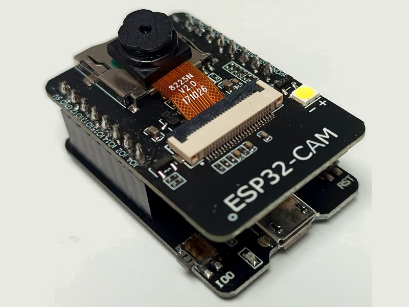
ESP32 CAM WiFi Module with OV2640 Camera 2MP and CAM-MB Adapter
SKU: SPKMIC004 · Category: Microcontroller › Espressif
RWF 20,000
In stock
The ESP32-CAM is a complete, palm-sized camera computer. It combines the ESP32-S module — the same dual-core Tensilica Xtensa® LX6 processor (up to 240 MHz) found on our ESP32 development board — with a 2-megapixel OV2640 camera, a microSD card slot and a bright LED flash, all on a board about the size of a matchbox.
With Wi-Fi and Bluetooth built in, plus 4 MB of extra PSRAM for handling images, it can stream live video to your browser, take photos and save them to a microSD card, or send pictures over the internet. That makes it ideal for security cameras, doorbells, time-lapse projects, plant and wildlife monitors, and simple face-detection experiments.
This ESP32-CAM has no USB port of its own, so this kit includes the ESP32-CAM-MB adapter. Simply plug the camera board on top of it: the adapter adds a micro-USB port, a CH340 USB-to-serial chip and the buttons needed for uploading code, so you can program it straight from the Arduino IDE without extra wiring.
Features
- Dual-core 32-bit ESP32 processor, up to 240 MHz
- 2 MP OV2640 camera, up to 1600 × 1200 (UXGA) resolution
- Image output in JPEG, BMP and grayscale
- Wi-Fi 802.11 b/g/n (2.4 GHz) and Bluetooth 4.2 (Classic + BLE)
- 4 MB PSRAM for smooth image capture and streaming
- MicroSD card slot for storing photos and video frames
- Onboard PCB antenna plus IPEX connector for an external antenna
Specifications
- Module: ESP32-S (AI-Thinker)
- Core: Tensilica Xtensa® Dual-Core 32-bit LX6, up to 240 MHz
- Memory: 520 KB SRAM + 4 MB PSRAM
- Flash memory: 4 MB
- Camera: OV2640, 2 MP
- Wi-Fi: 802.11 b/g/n, 2.4 GHz
- Bluetooth: v4.2 BR/EDR and BLE
- Power input: 5 V (via adapter USB or 5V pin)
- Logic level: 3.3 V
ESP32-CAM Pinout
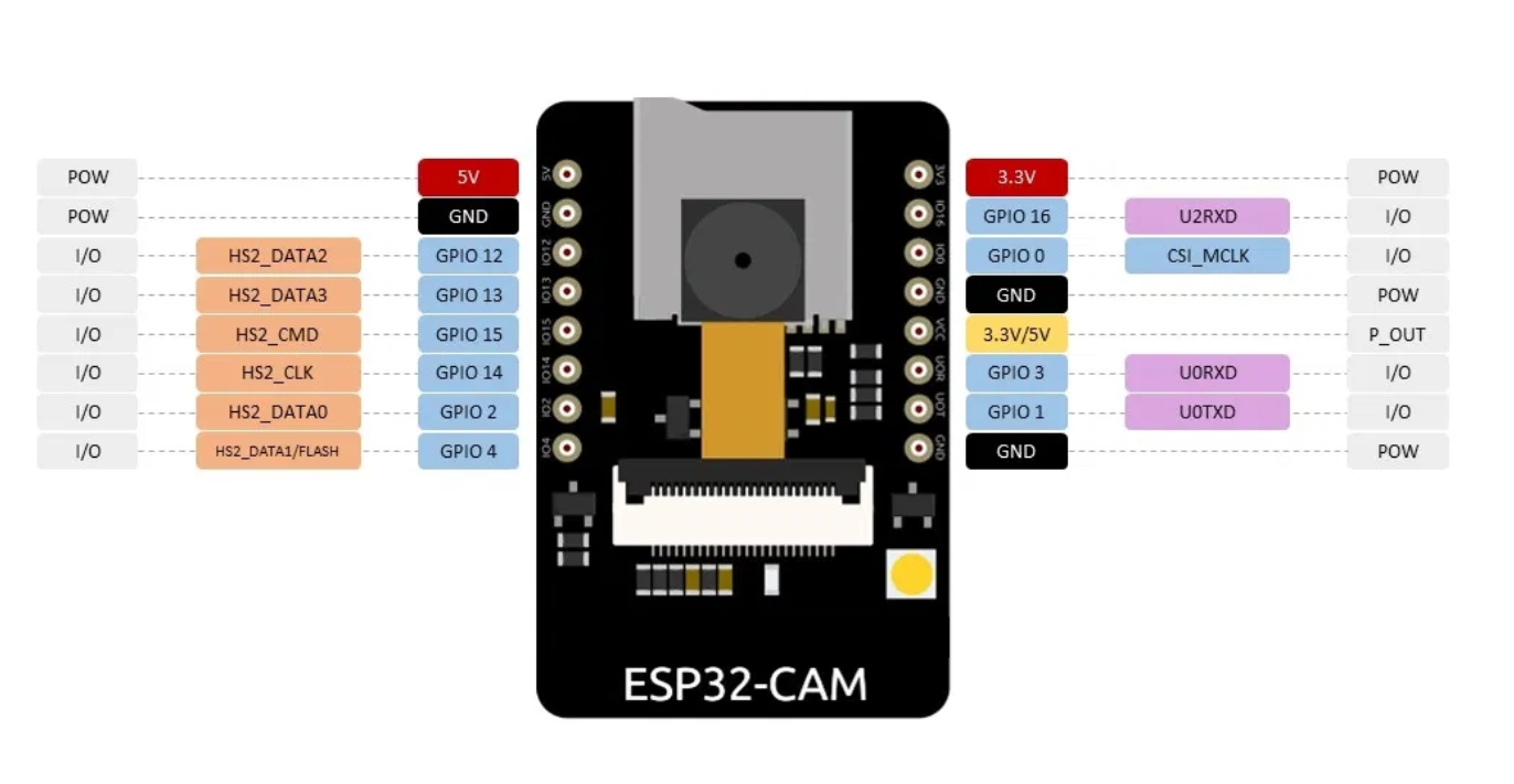
- GPIO0 decides the boot mode: connected to GND = upload (flash) mode; left free = run your program. The CAM-MB adapter handles this for you.
- GPIO 2, 4, 12, 13, 14 and 15 are used by the microSD card. If you don't use a card, they are free for your own circuits.
- GPIO4 also drives the flash LED, so it will light up when the microSD card is active.
- GPIO16 is used by the PSRAM — don't connect anything to it.
Getting started with ESP32-CAM
Since the ESP32-CAM uses the ESP32 chip, start by installing the ESP32 board package exactly as described on our ESP32 development board page. If ESP32 doesn't appear in the Boards Manager, add this link under File › Preferences › Additional Boards Manager URLs:
https://raw.githubusercontent.com/espressif/arduino-esp32/gh-pages/package_esp32_index.json
- Plug the ESP32-CAM onto the CAM-MB adapter, matching the pin labels on both boards (5V to 5V, GND to GND). The camera faces up.
- Connect the adapter to your computer with a micro-USB data cable. If no port appears, install the CH340 driver and reconnect.
- Click Select other board and port, search for AI Thinker ESP32-CAM and select it along with the adapter's port. Or use Tools › Board › esp32 › AI Thinker ESP32-CAM.
- Open the built-in example File › Examples › ESP32 › Camera › CameraWebServer.
- In the camera-model list (in the sketch, or in the board_config.h tab on newer versions), make sure only CAMERA_MODEL_AI_THINKER is active, then enter your Wi-Fi name and password — see the lines below.
- Click Upload. If you get “Failed to connect”, hold the IO0 button on the adapter, tap RST, and release IO0 when “Connecting…” appears.
- Open the Serial Monitor at 115200 baud and press the RST button. Copy the IP address it prints, open it in a browser on the same Wi-Fi network, and click Start Stream.
The only lines you need to change in the CameraWebServer example:
// Select camera model — keep only this one uncommented
#define CAMERA_MODEL_AI_THINKER  // Has PSRAM
// Replace with your network credentials
const char *ssid = "YOUR_WIFI_SSID";
const char *password = "YOUR_WIFI_PASSWORD";
Upload the code into your board and when it finishes, in the serial monitor will be displayed an IP Address. Copy it and paste into your browser's search box then hit enter. And you'll an interface allowing to use facial detection and streaming features.
Good to know
- Use a solid 5 V supply (at least 2 A when powering from the 5V pin). Most “brownout detector” resets and unstable streams are caused by a weak power supply or a long, thin USB cable.
- The board gets warm while streaming — this is normal.
- Remove the plastic film from the camera lens before use for a sharp image.
- For better range, connect an external 2.4 GHz antenna to the IPEX connector (this may require moving a small resistor on the board to switch antennas).